Indie game storeFree gamesFun gamesHorror games
Game developmentAssetsComics
SalesBundles
Jobs
Tags

DJL54

27
Posts
7
Topics
A member registered Nov 16, 2020

Recent community posts

Hi Charlie,

Yes you have explained it very well.  I now understand more about canvas resolution and the raster layer resolution and what effect each has.  Very detailed explanation as always.   

Thank you

Doug

Hi Charlie,

Working on getting lowest possible resolution and maintaining the detail required.   I start with a canvas at 200 ppi, import an image, create all  my tool paths.  Save as a new file then I change the ppi in the canvas to 100 ppi and regenerate all the tool paths.  Even though the image was imported to a canvas at 200 ppi in the original file, will the tool paths be generated as if the image was imported at 100 ppi as that is what the canvas ppi is at in the second file.  Or should I be importing the image into the second file with the canvas set a 100 ppi - creating a new file from scratch at 100 ppi?

Doug

Hi Charlie,

Yes just a 30 or 60 deg v-bit.  V-bit has is a true v-bit - no round over on the tip.  On the penguins I used a 60 deg bit.  On the portrait one I used a 30 deg bit as it had some cuts that had close to vertical sides.  The 30 deg bit can go deeper when the cut has close to a vertical side.  Yes very small stopover (0.0075 inches).   The small step over means that even with the deepest cuts (0.20 inches) the bit is not overloaded as it is only taking off 0.0075 inches of material.

The only cleanup I do is to blow off the dust when I take it off the CNC.

I spend more time building the frame and LED light panel (3/8 acrylic surrounded by LED lights) that goes behind the carved panel.  For a switch I use an RF remote control in the base.

In PixelCNC the canvas is at 200 ppi - maybe helps with the detail of the carving??  Still playing with PixelCNC settings.

Doug

(1 edit)

The material is 1/4 inch thick with the deepest cut being 0.20.  That leaves 0.05 of material for the deepest cuts which are the whitest part of the picture.  The black part of the picture has no material removed with shades of grey in between.  The imported raster image is inverted to get the correct depths in the model - white low and black high.

Doug

Hi Charlie,

Corian is the brand name for a solid surface counter top material made by Dupont.   It comes in different colors and designs.  I use the Glacier White as it is a solid white material.  Apparently there are other similar products that works just as well - candlestone is one that I have seen referred to when researching Lithophanes.   It cuts easily - I have used both 60 deg and 30 deg v-bits.  I use a parallel carving operation at a 45 deg orientation with 0.0075 step over.  With the 45 orientation I don't do a roughing  pass.   Doesn't make chips with that small of a step over but so far it has worked for me.

Doug

Latest Pixel CNC work - couple of lithophanes in 1/4inch Corian backlit with LEDs around a clear acrylic plate.  First two photos are backlit, the second two not backlit


\56742198

]

Hi Charlie,

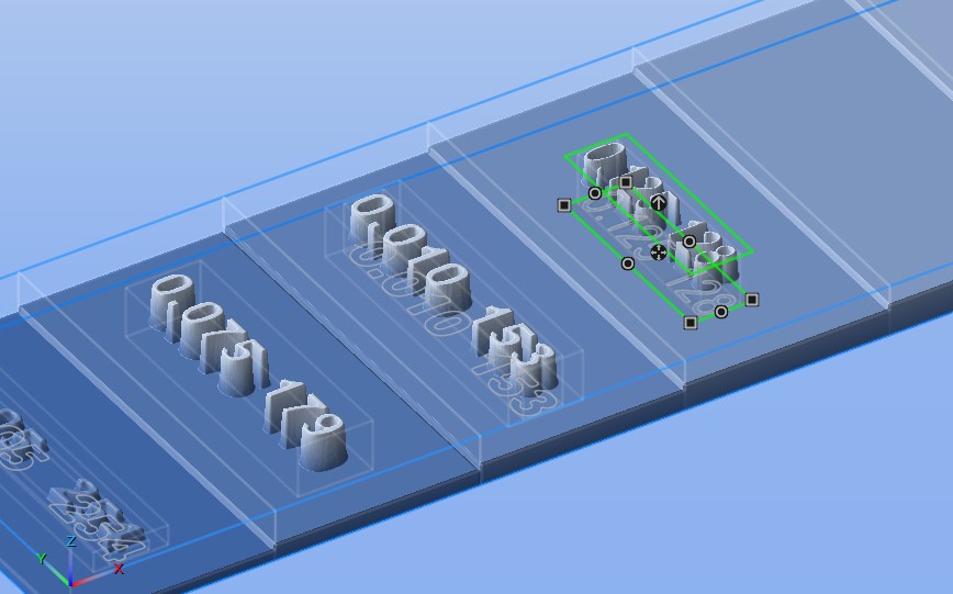
Still having issues with this file.  Bit of a change in plans as I could not get the text Trace to Paths to work.  I think I have set up the Text Layers incorrectly  so just gong to use Blend = Subtractive and use a ball nose bit to carve out the text. My work flow is as follows:

  1. Create a Canvas 9 X 2 X 0.25
  2. Create the stepped “profile” by creating a Raster Layer for each section with the Origin at 0.0 and the Z-Size the height that I want each section to be – eg 0.050, 0.075, 0.100 and so on.
  3. Create a Text Layer for each corresponding Raster Layer.  I want the text to be 0.010 deep so I tried making the Text Layer with a Z-Size of 0.010 with the Origin 0.010 below the top of the corresponding Raster Layer.  Using Subtractive this makes the entire Text Layer lower than the top of the Raster Layer and the actual text lower more.  See TextLayer 0.200 in the attached image
    1. Top of Raster Layer -0.050
    2. Top of Text Layer -0.100
    3. Topo of actual text -0.110
  4. I thought the Top of the Text layer and the Raster Layer would be the same?  The only way I can get the Top of the Text Layer and the top of the Raster Layer to be at the same Z-height is to make the Z-Origin 0.24 for all the Text Layers.  Is this what I should be doing or have I gone totally off the rails.

Thought I had Layer Groups figured out.  I have all the layers in Group 1 and the Text Layers also in Group 2.  Selecting Group 1 shows everything as expected.  Selecting Group 2 shows the boundaries of the text layers but no text?  When I go to Project Operations and select Group 2 nothing shows?  What have I done wrong?

I want to do a clearing pass with a 0.25 bit then a final pass with just the text.  This does not work with Group 2 so I use Group 1 (all layers).  REST Machining is turned on so just the text should get carved but passes are also made at each change of height.  Leave Stock is set to 0.001 to ignore some “artifacts” that show up on the flat surfaces.  Once again where have I gone astray?

I wanted to attach my file but don't see how to do it in a Reply?

As always any and all suggestions very much appreciated.

Thank you

Doug

Hi Charlie,

Yes, adding paths to the Layer Groups would be beneficial  for me as I use the Paths Layers for a quite a few tool paths.   Right now I just merge “common” Path Layers but keeping them separate and put in a group would make editing each Path Layer easier.   Perhaps others don’t use Paths for creating tool paths so don’t know how widely it would be used.  Might want to make more Layer Groups - only 8 may not be enough?

Doug

(1 edit)

Hi Charlie,

I would like to engrave text on the surface of raster layers at different levels.  I have created each level as a separate Raster Layer and then placed text on  the surface.  What I want to do is engrave the text 0.010 deep into the raster layer.  I create the Text Layer and Trace Text to Paths and then use this Paths Layer for the Project Operations.  The way I have been able to make it work is to use the Medial Axis Carving and play around with the Depth Offset to get close to what I want.   Being Medial Axis Carving the depth of the text varies (as it should) but this not what I am trying to achieve.  Is there a way to get a Paths Layer of test as a single line font and then use either Paths Carving or 2D Profile Milling to engrave the text.  Right now if I use the Paths Carving or 2D Profile Milling the tool path is at the top of the Canvas instead of the top of the Raster Layer and I can't figure out how to get it to cut into the top of the Raster Layer.  In all cases the text on the Paths Layer ends up as a two line font as it is derived from the Text Layer.  So after all the verbiage above my end goal would be to have a single line font that I can engrave with a v-bit on the top of each Raster Layer.    If this is not possible I think (haven't tried it yet) I could leave the text raised by 0.010, combine all the layers and do a Parallel Carving Operation with a v-bit with a small step over - just would take a long time. Screenshot attached.

Thank you 

Doug

Hi Charlie,

Latest update was great - especially the raster layer changes - area selection and ability to create new layers from the selection.  Also to be able to view all path layers when editing a paths layer.

I like the Group Layers feature in the Project Operations but am finding a bit of an issue in the Project Canvas.   When using the Layer Groups only the Layers on the Group selected are visible.  If I have several Groups I can only view one at a time.  My current method is to put all the layers in Group One for work in the design space and then separate them  into Groups for the Project Operations.  Am I missing something? Am I correct that Paths Layers are always visible in the Project Canvas and cannot be assigned to a Layer Group?

Thank you

Doug

test post

Hi Charlie,

The post processor worked!  Thank you so much.  Now I am palying with the origins and canvass size and importing a jpg to see how I manage with the program.  Looking at one of your videos (horizontal roughing and parallel finishing)  it seems that I just load a jpg, set a few parameters, create tools and operations and am good to go.  Seems too easy?

Doug 

Hi Charlie,

https://pastebin.com/BR5MSaH  is the link.  called example NC file.

Thank you so much for helping me out .

Doug

Hi Charlie,

Running an Axiom Iconic 8.  Table size is 23.81 inch (X), 47.63  inch (Y), 3.937inches of Z.   ( 610 mm x 1210 mm x 100mm).  Using a RichAuto B11 DSP controller.  Home is at the front left corner and I home the machine on every start up.  Today I tried moving the origin to the center of the table and the Y soft limit no longer came up as an error.  Tried setting Z = 0 as high as possible and at the spoilboard.   In both cases still getting errors of X soft limit and Z soft limit.  From what I understand, the controller thinks the file is too big for the machine.  Not sure if it is an imperial/metric thing as the controller works in metric.  In PixelCNC I did change the canvass dimensions to be metric.  The only thing that was not metric was the tool size.

Doug

Hi Charlie,

I have tried the softeare and am stuck at gettign a g-code file that will work with my CNC.  I have tried the different post processors that you include with the program.   I have also tried the one I normally use in Fusion 360 - RS274.  They all give me the same error when I try to run the file from the controller ---  "out of soft limits"  for all three axis.  Is this a problem with how I have set up the work area.  I have tried to change the size but still get the same errors.    At a loss as to what to do next.

Thank you

Doug

Did some more testing this morning.  PicelCNC will run on the Intel HD GPU as long as I don't have my USB dock plugged into the laptop.  So your program works as you expected.  It is my hardware configuration - USB docking station and second monitor.

Next quetsion - how do I load an image.  I know I am missing something simple.

Thank you

Did some more experimenting:

1.  Unplug laptop  from USD docking station

2. Load PixelCNC - loads fine on laptop.

3  Plug laptop back into USB docking station - second monitor (BenQ) comes alive and there is the PixelCNC program.  Seems to work - just tried a few menu selctions - did not do any actual work.  Can drag window between monitors.  So I have a pretty easy workaround to get the program onto my bigger monitor.  Will go with that.  

I posted the latest log file to Pastebin.  Here is the link https://pastebin.com/GdQafMwb

Looks like I was successful in changing the GPU but had to do it in the NVIDIA Contol Panel.  Changed ita globally and also for PixcelCNC.  Not sure why it still shows as the Intel HD for the laptop and USB3.0dual display for the BenQ monitor when I look at the praphics settings in Windows.

I am thinking the USB docking station is the thorn in the side.  I have not tried connecting the BenQ monitor directly to the laptop.  Another day perhaps. 

Here is the link for the log file.    https://pastebin.com/QWp2xTtj

looked at Hitman and could not find where  to add to a list of allowed programs

Thank you for the detailed help tips.

Originally ran the .exe file from a folder called downloads.  All files were unzipped - 16 files and 3 folders.   Moved to the desktop and no difference.  Tried from C:\PixelCNC and no difference.  If I run as administrator it asks me if I will allow Pixel CNC to make changes.  When I do not run as adminsitrator I do not get that splash screen.


I am working in native windows - not sure what those other things are so I am sure I am not using them.

log file is very long but the config.dat file does load when run from the desktop and from  C:\PixelCNC

  first few lines of log file - I do not know how to attach the file to this reply.

0.017  
0.017  [ PixelCNC v1.43a Trial 64-bit  - Jul  1 2020 ]
0.018  [ Charles Van Noland - http://pixelcnc.deftware.org ]
0.019  
0.019 exe: C:\PixelCNC (64-bit)
0.020 user: C:\Users\Lunty Laptop\AppData\Roaming\Charles Van Noland\PixelCNC
0.021 log: 201116-213231
0.022 --- initializing ---
0.022 configuration...
0.022 config_init: default version #143
0.023 loaded 5.258kb from "C:\Users\Lunty Laptop\AppData\Roaming\Charles Van Noland\PixelCNC\config.dat"
0.025 LOADED CONFIGURATION:

did get the message that I was using th trial version and my 20 minutes was up 

I run Bit defender, Malawarebytes and Hitman  for anti virus software.

Does not show up in my APPS for Windows 10 so I don't think it gets installed. 

Screen shot of what I get when I try to install.


config.dat not congig.dat

in path name all vertical lines "|" should be "\"| 

portion of log  file. cannot attach an image or cut an paste with out getting an error about "expecting 0 to 20---- characters

0.027 failed to load "C:\Users\Lunty\Lunty Laptop|AppData|Roaming\Charles Van Noland\PixelCNC\congig.dat

Doug

Trying to download the trial but get a screen with no fonts.  Running as administrator makes no difference.  Tried previous versions and no difference.

Graphics card is NVIDIA GeForce GTX 1050.  Computer is 

Processor:  Intel(R) Core(TM) i7-7700HQ @2.80 GHz 

Ram: 16.0 GB

System Type: 64 bit OS 


Any ideas ???

Doug